Point Cloud Case Study
3D Point cloud survey
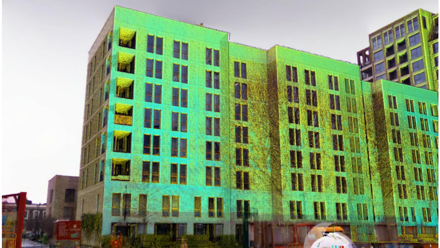
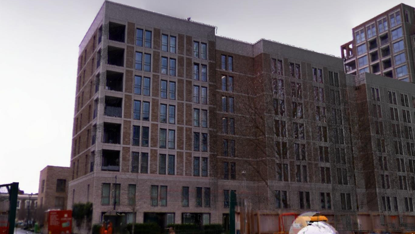
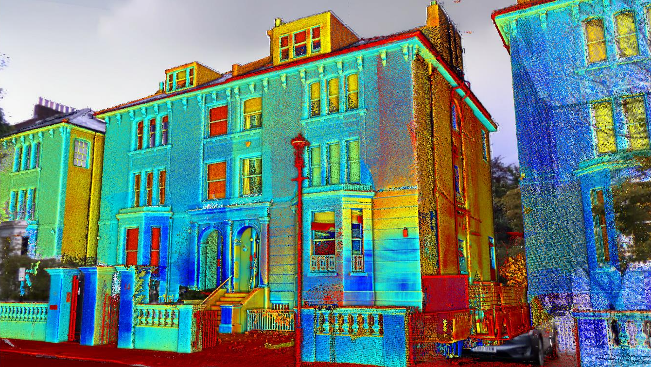
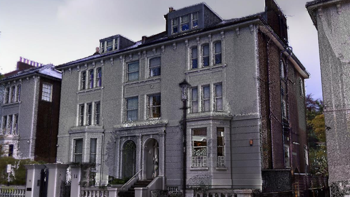
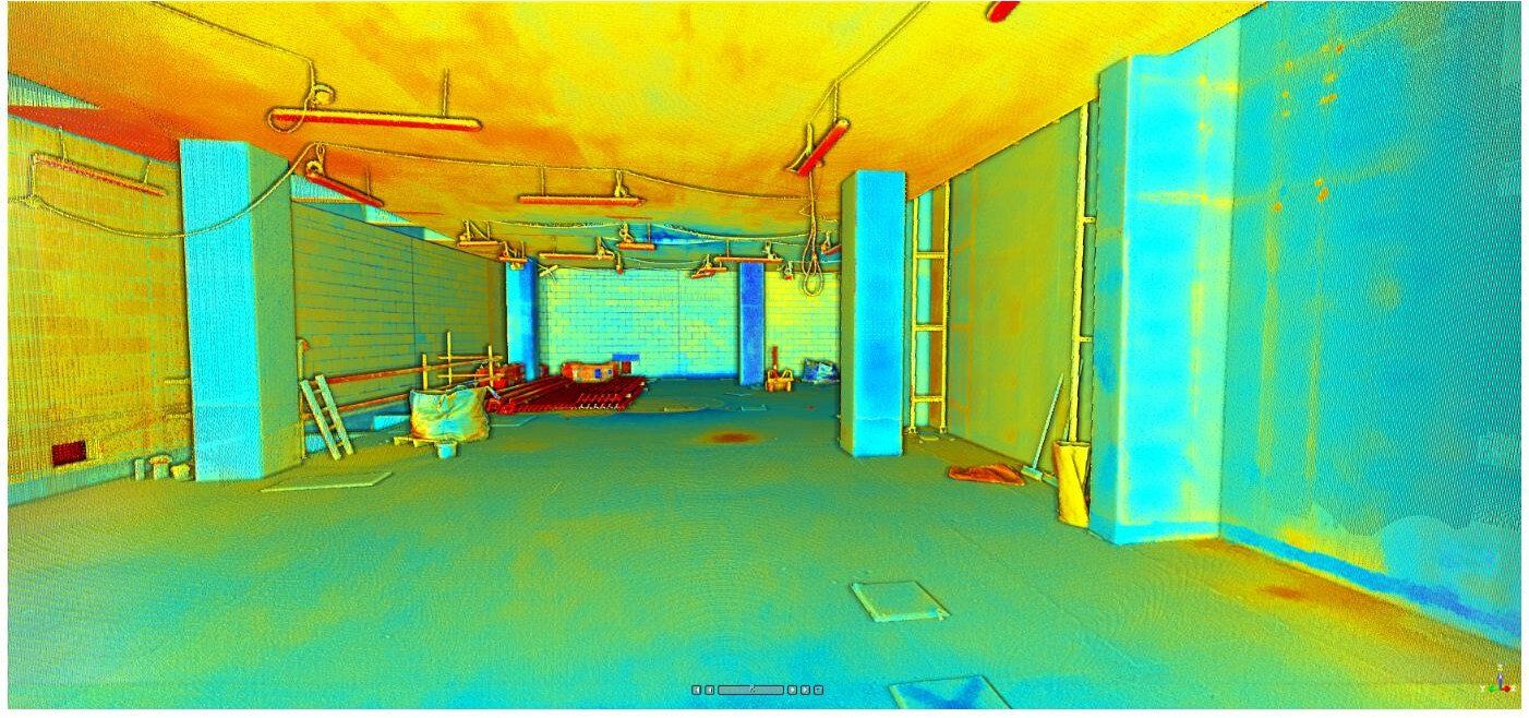
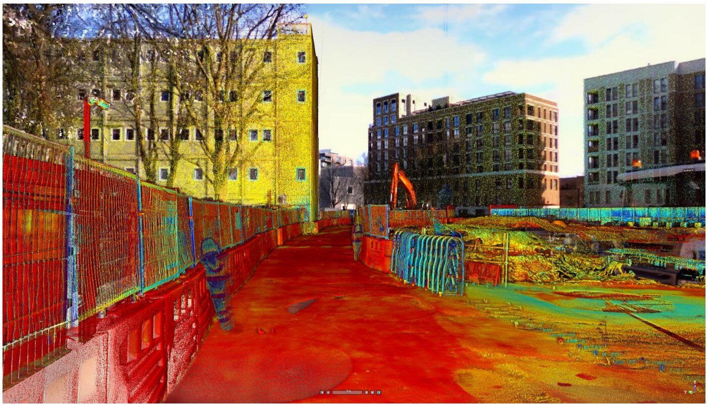
Point clouds are a digital representation of real objects/spaces displayed as a set of data points in space. They are obtained using specialist surveying equipment which completes and ties together a set of 360 degree scans to 2mm accuracy.
They can be produced for any kind of physical spaces such as buildings, outside areas, roads, etc.
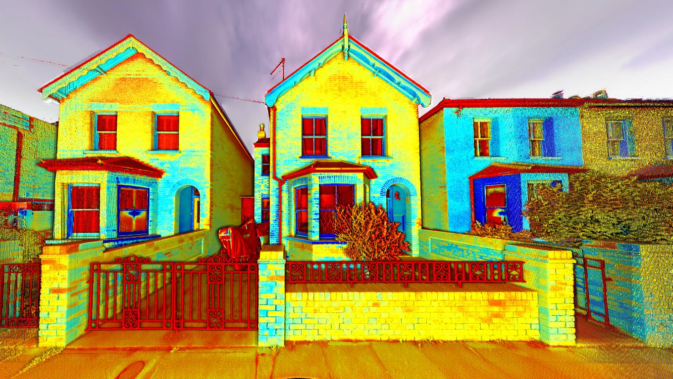
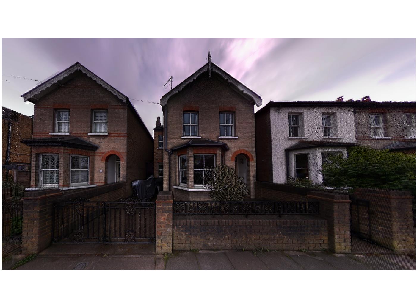
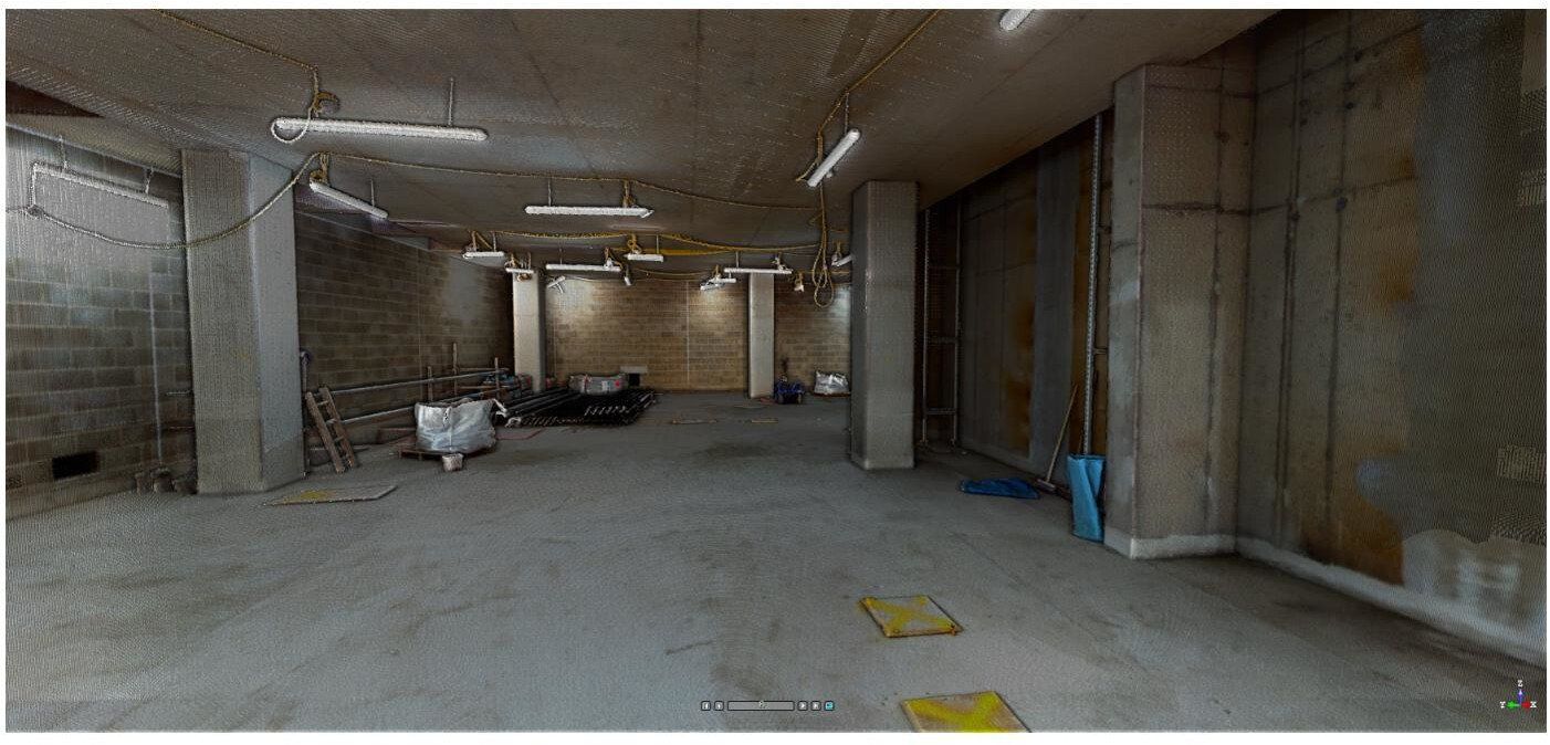
Point cloud can be colourized to define and display material and georeferenced so each point has a true coordinate and level.
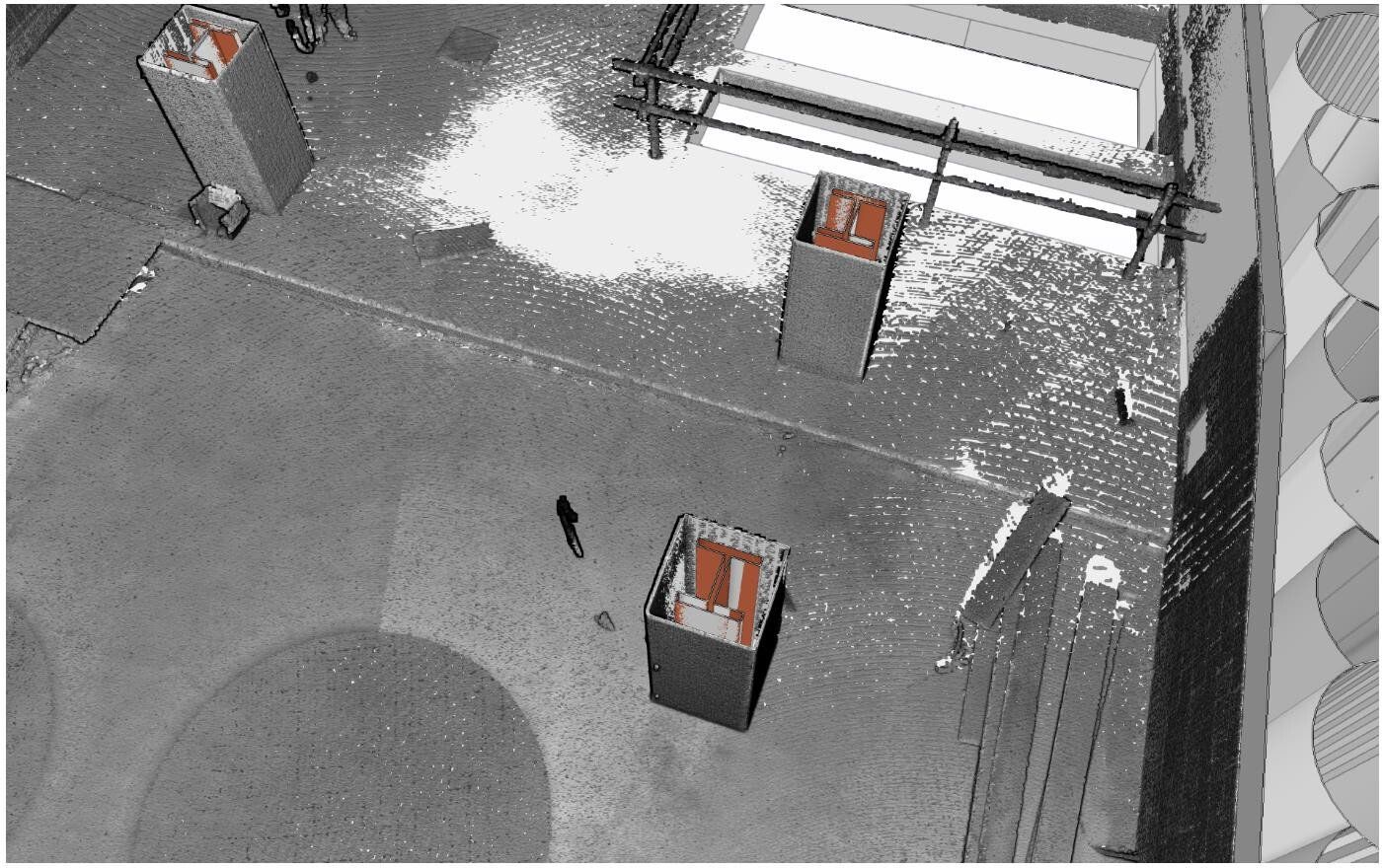
It is also possible to clean and classify the cloud from unwanted "noise" data such as furniture and trees to only show the desired object/s.
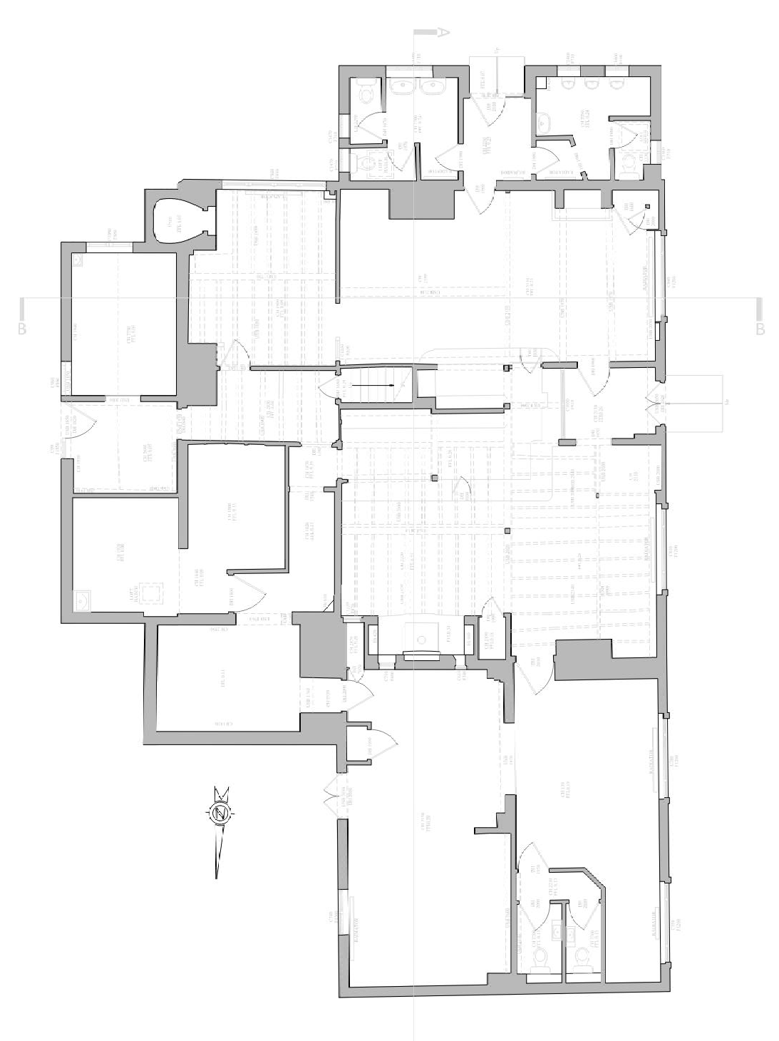
Producing 2D As-Built Surveys
Where a 2D As-built survey is required of a physical space, the area can be scanned to obtain a 3D point cloud. The information from the point cloud can then be used to produce 2D As-built drawings quickly and accurately with AutoCad.
This system eliminates the need to re-visit site for additional or missing information as everything is already stored in the point cloud, and can be easily accessed with Cad, Revit, Tekla and other common design software.


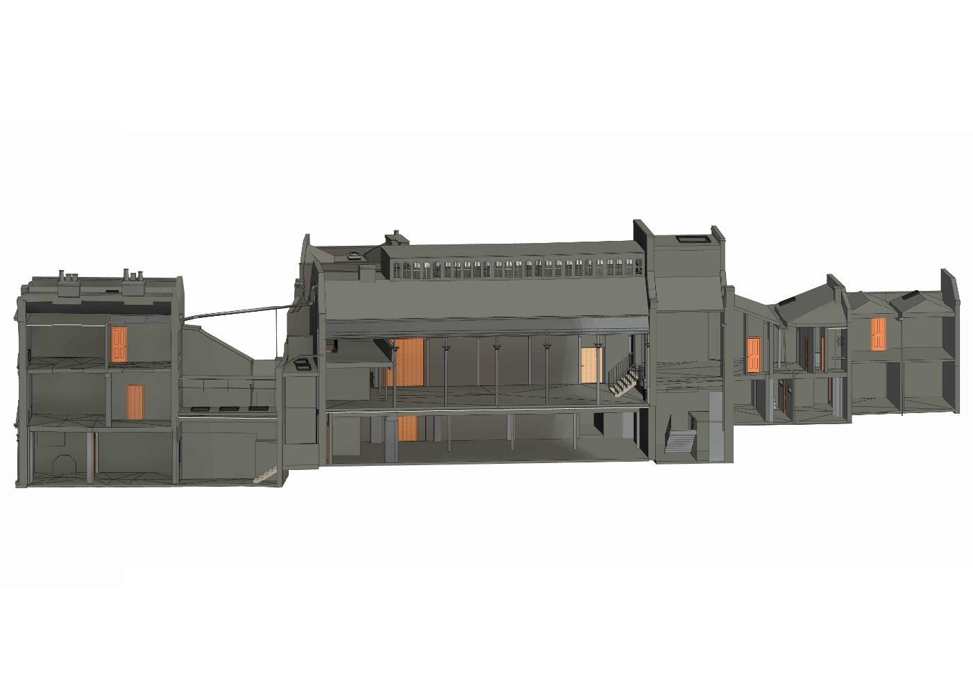
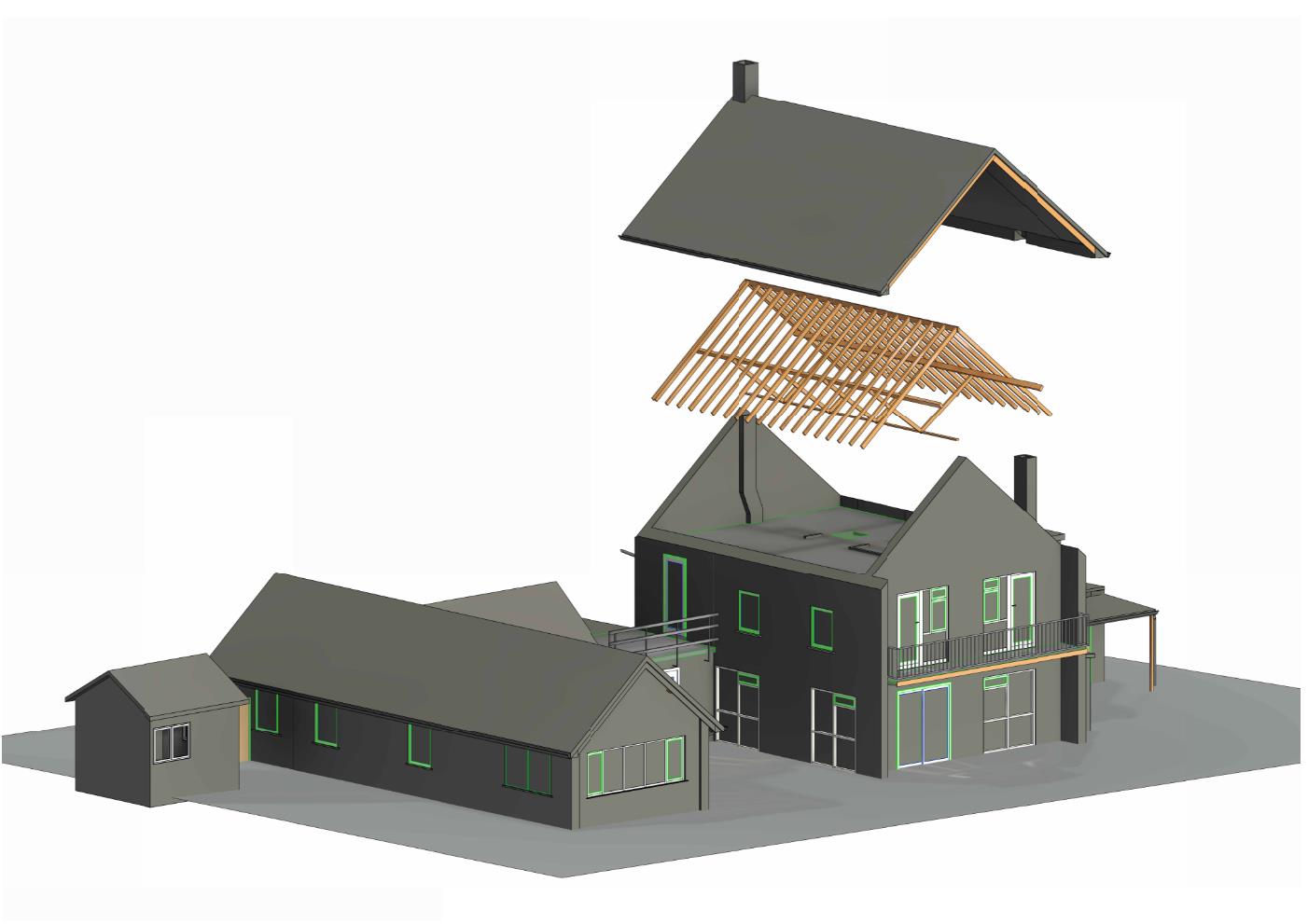
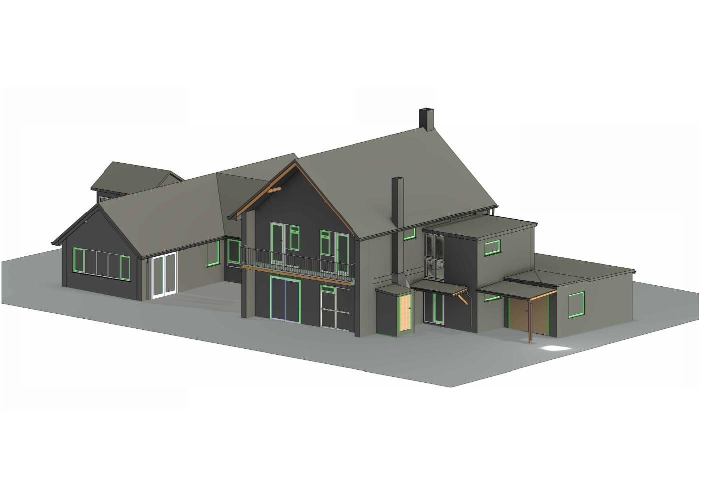
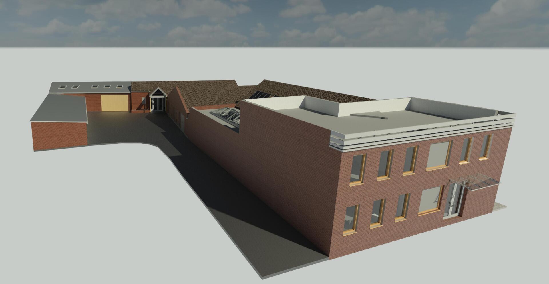
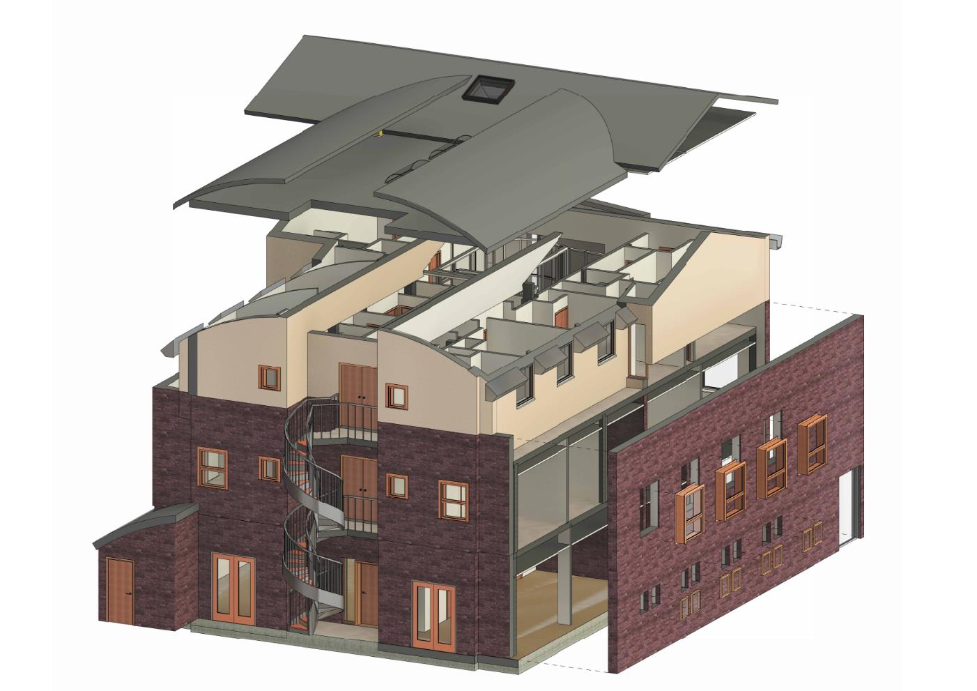
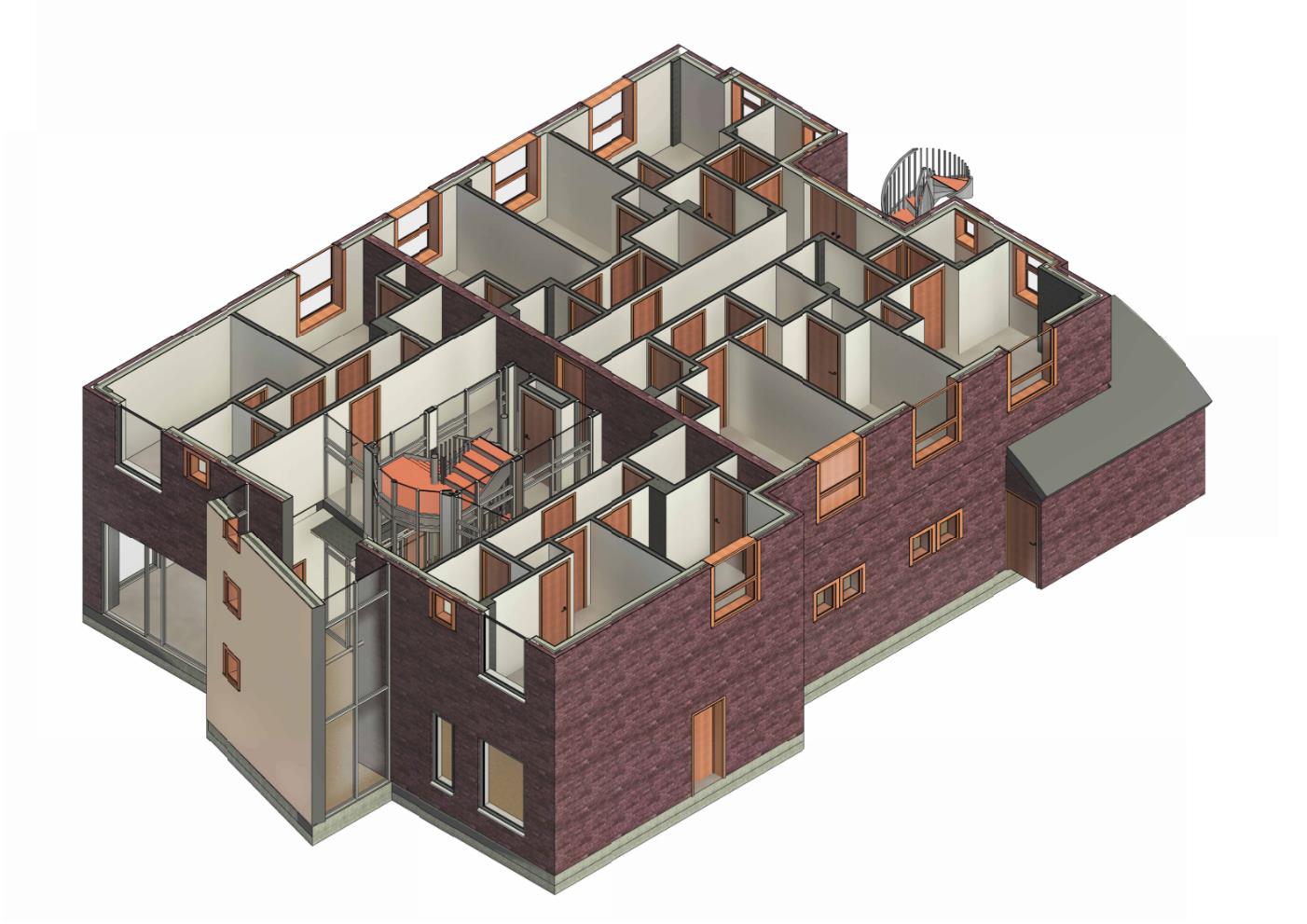
Revit As-Built Models
A 3D point cloud scan can also be used to generate Revit models. In a retrofit project, these can be used as a base model for architects, engineers and any other consultant to accurately work and develop new designs for the space.
Using traditional surveying methods to collect all the information needed to develop this kind of 3D model is time consuming, often with fragmented and incomplete data. The quality of the survey is limited by the surveyor and their interpretation of the requirements. As a result of this, modelling time can increase with the open possibility of inaccuracies and re-surveys.
By scanning the object, all the relevant information are stored in a single file and easy to access. Typically a one day site visit is sufficient to collect all the necessary data to develop a model.
After scanning the project BES can develop Revit models up to and including LOD 300 Standard Survey Modelif required.
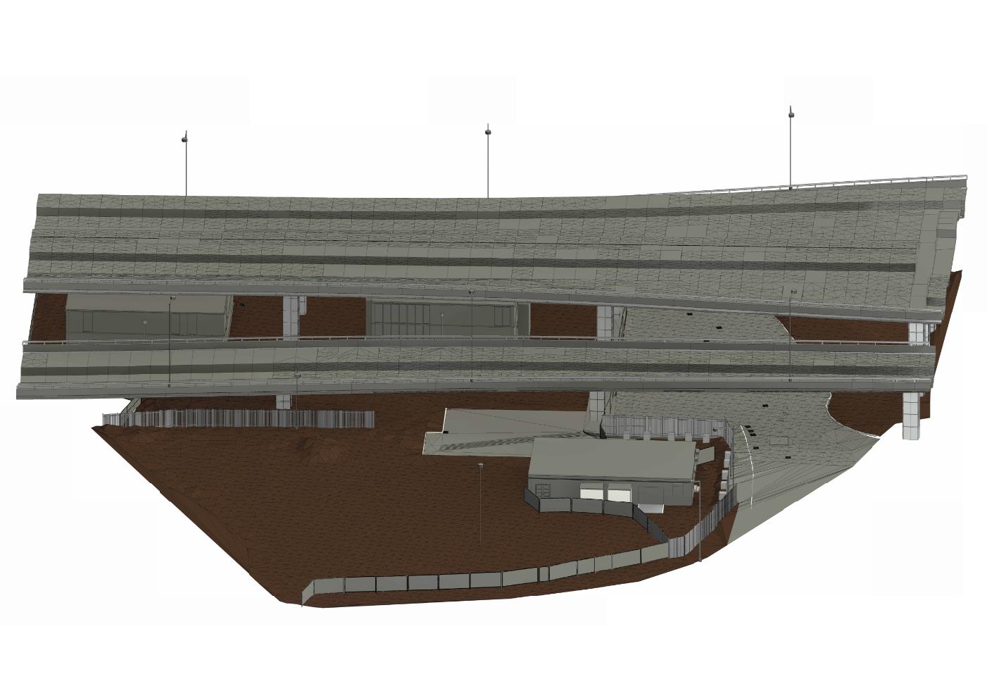
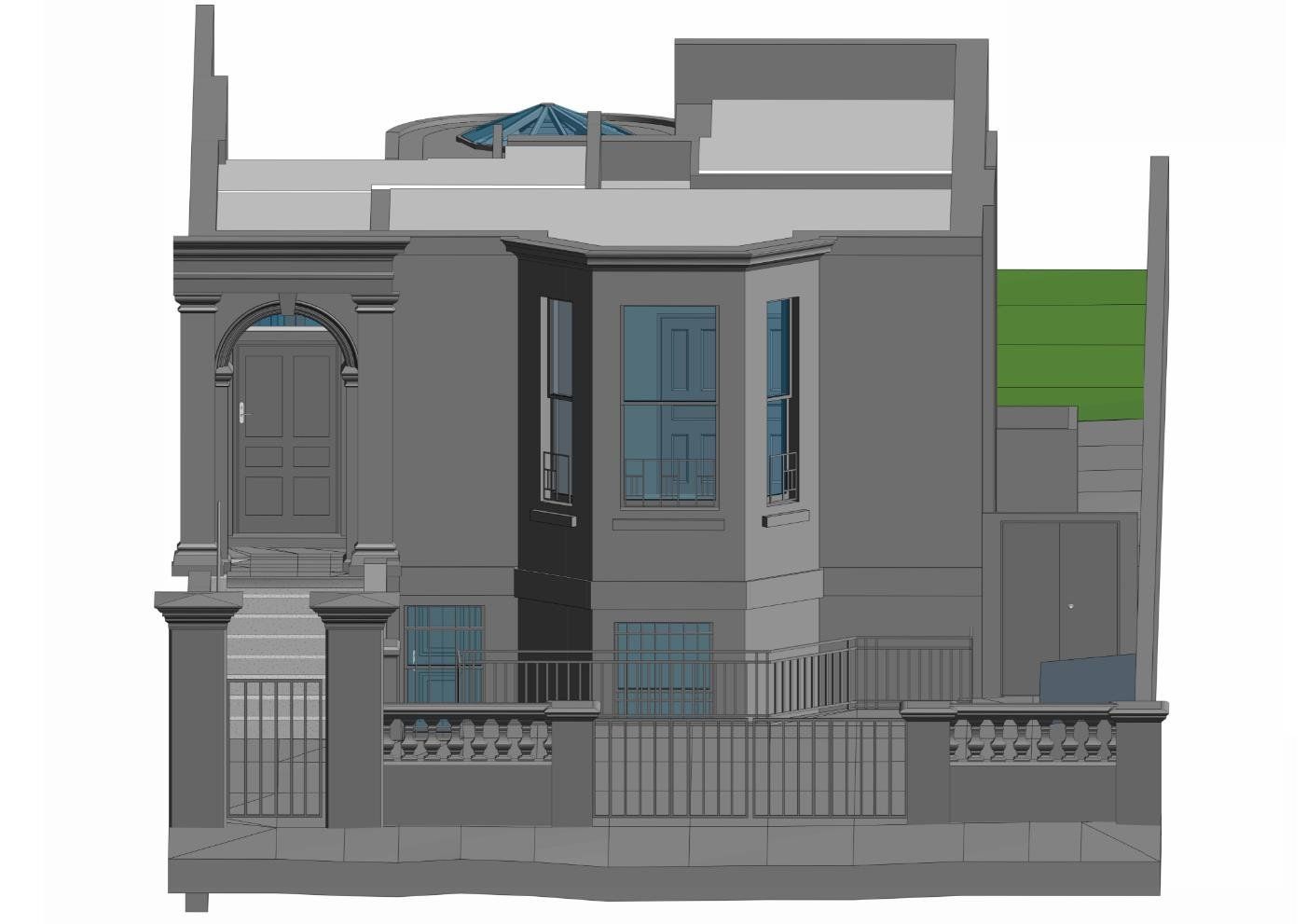
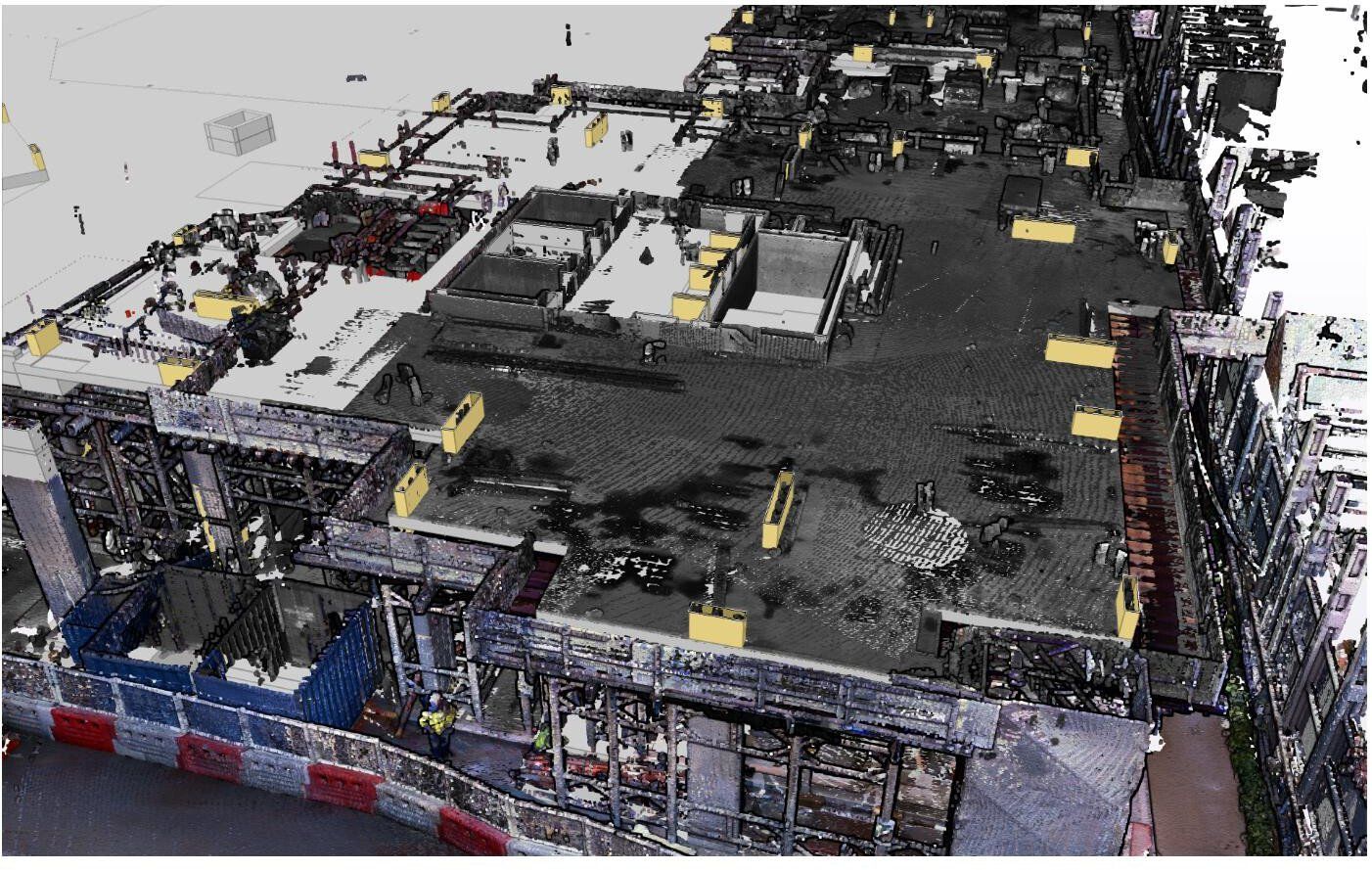
Utilizing Point Clouds directly for analysis
If required, BES can provide a 'point cloud only' service, and this can be used to work directly with almost all common design software packages such as Autocad, Revit, Tekla etc.
By working with the cloud, you are in control of what you want to see in the project.
With the point cloud, is it possible to:
- Start design process using PC as base. (example of steel designer)
- Verify as-built information
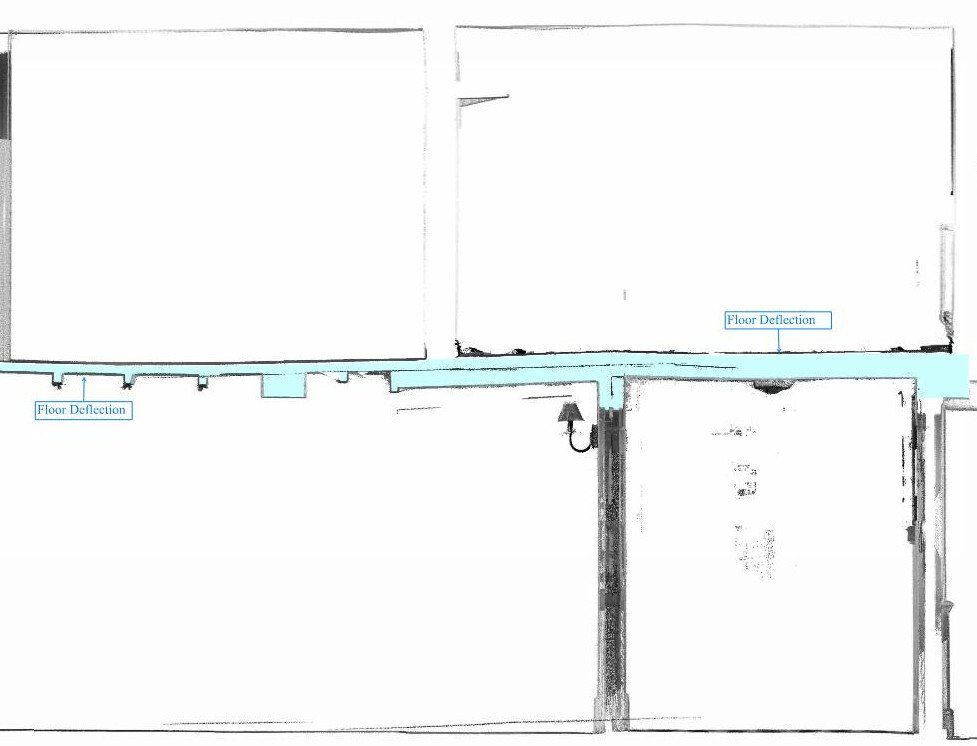
- Analyse structural walls verticality and deformation
- Analyse floor and ceiling deformation and irregularity
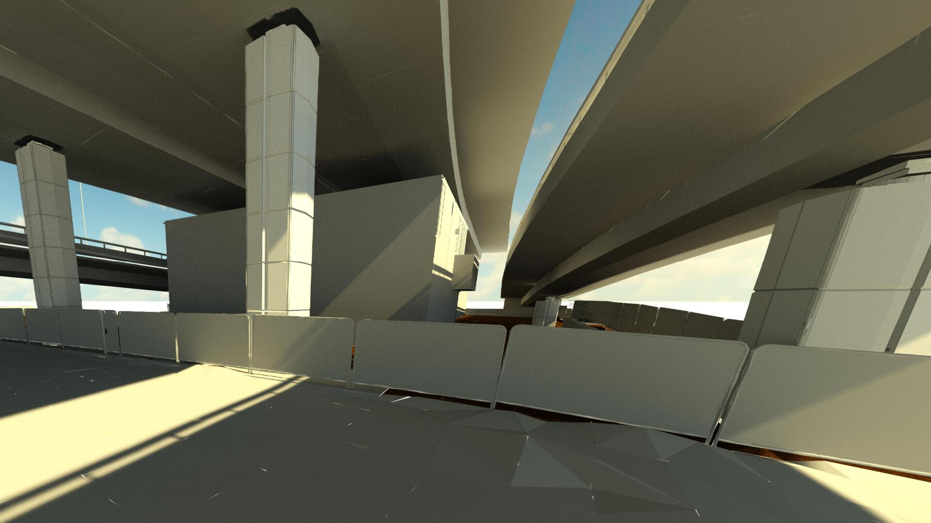
- Check the surroundings to understand site conditions
- Visualize and measure complex geometrical objects such as curved ramps, parabolic columns, etc.
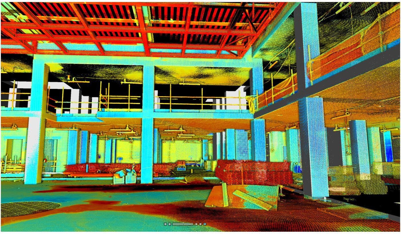
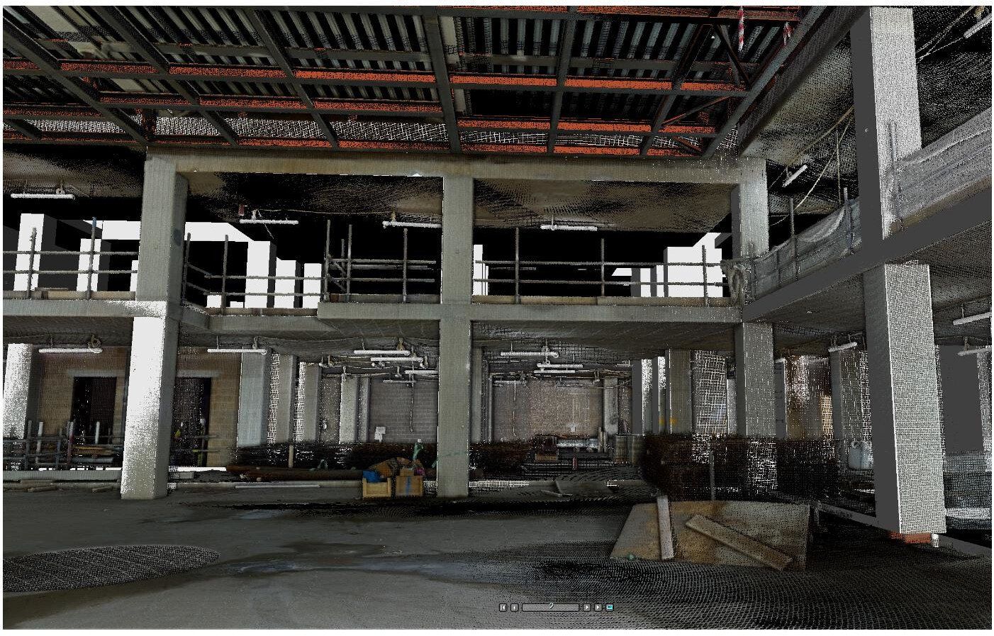
Working with a point cloud in a retrofit design project will allow you to visualize the whole structure and identify irregularities which cannot be spotted by a site visit or a traditional survey.
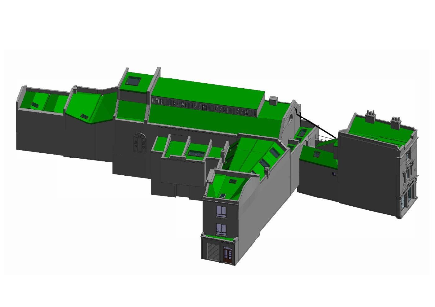
BES can also classify the point cloud and create layers to isolate necessary and unnecessary elements to help you visualize and work only with the required data.


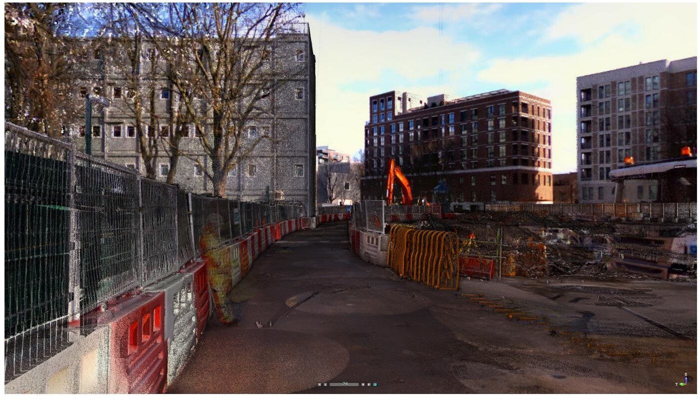
Construction Applications
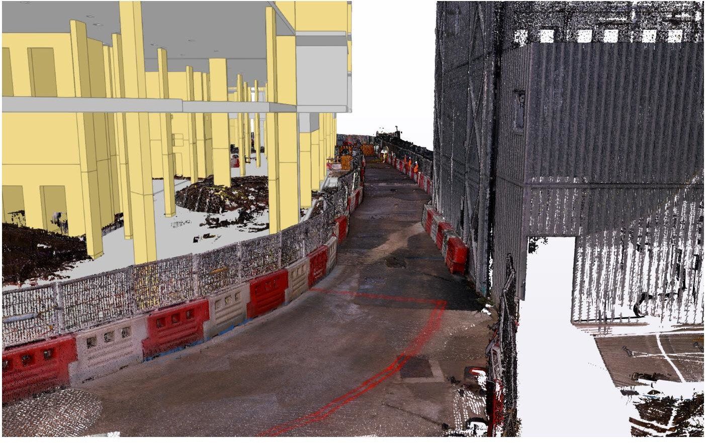
BES can perform point cloud scans on live construction projects which can then be viewed by themselves or overlaid on the design model by using free, commonly used software like Trimble Connect, Tekla BIMsite, etc.
This can then be used for:
- Recording site status and boundary conditions at the beginning of a project to quickly identify any issues which could lead to delays during the works.
- Recording completed works prior to the handover to a client.
- Capturing progress at a point in time, for analysis and future reference.
- Gathering evidential data for Party wall agreements
- Remotely surveying and recording actual quantities of materials used, e.g. calculating formwork material usage per square meter.
- Visualising site logistics clearly, with the ability to identify and measure 'pinch points'.
As a by-product of these scans, all the information needed to generate project as-builts can also be extracted without using site resources to perform surveys.
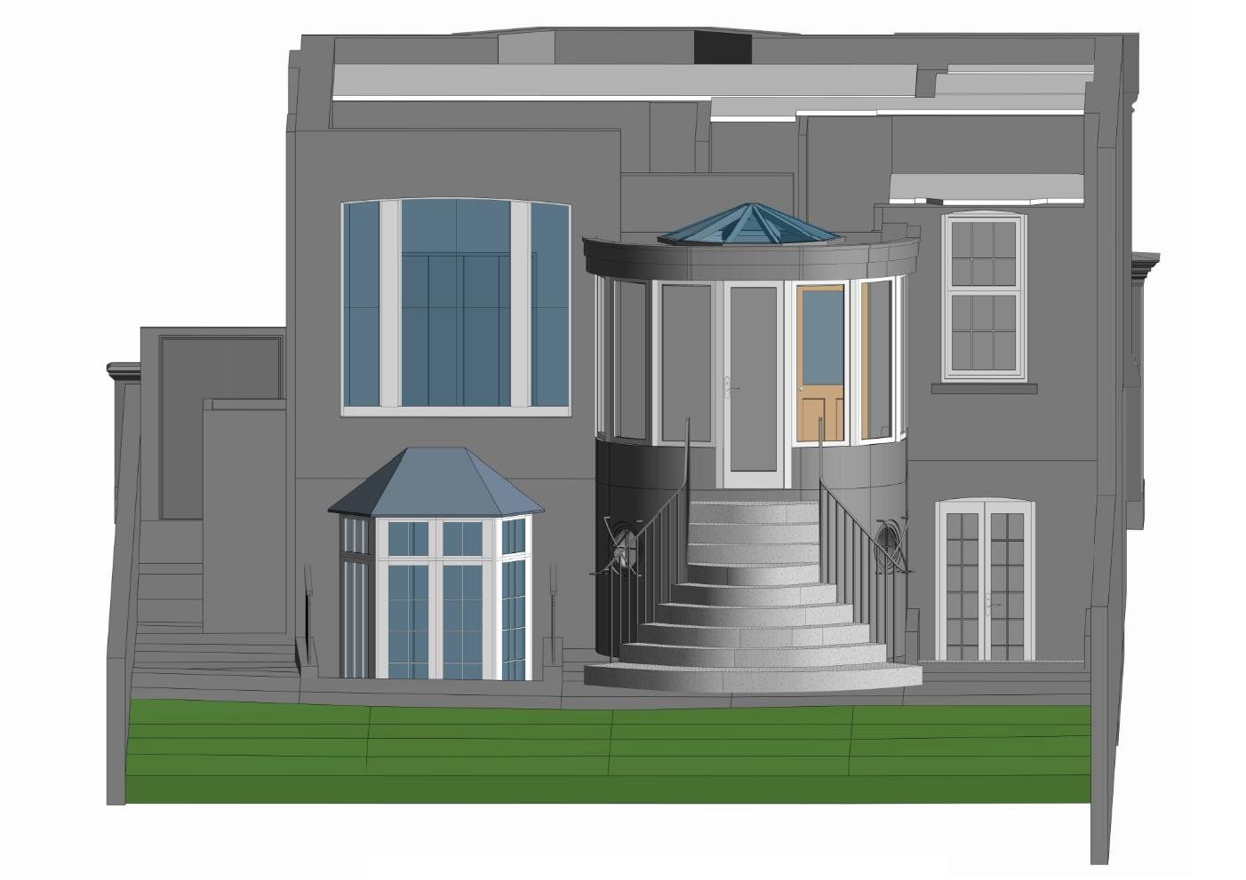
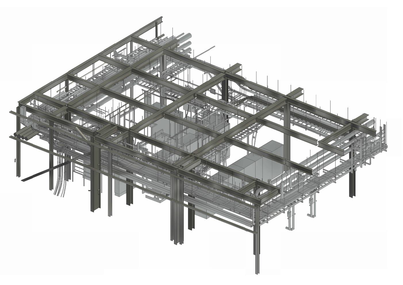
Generating 3D MEP Models
For MEP designers working on an plant extension/refurbishment, having an As-Built Revit model of the mechanical and electrical elements can assist with clash detection in the new design. Having this information at the start of the design process can avoid having to deal with design issues in the construction phase, reduce delays and control the overall cost of the project.
Geo-located Point Clouds
By using Control Points, we can correctly geo-reference projects to link registered scans to a project coordinate system
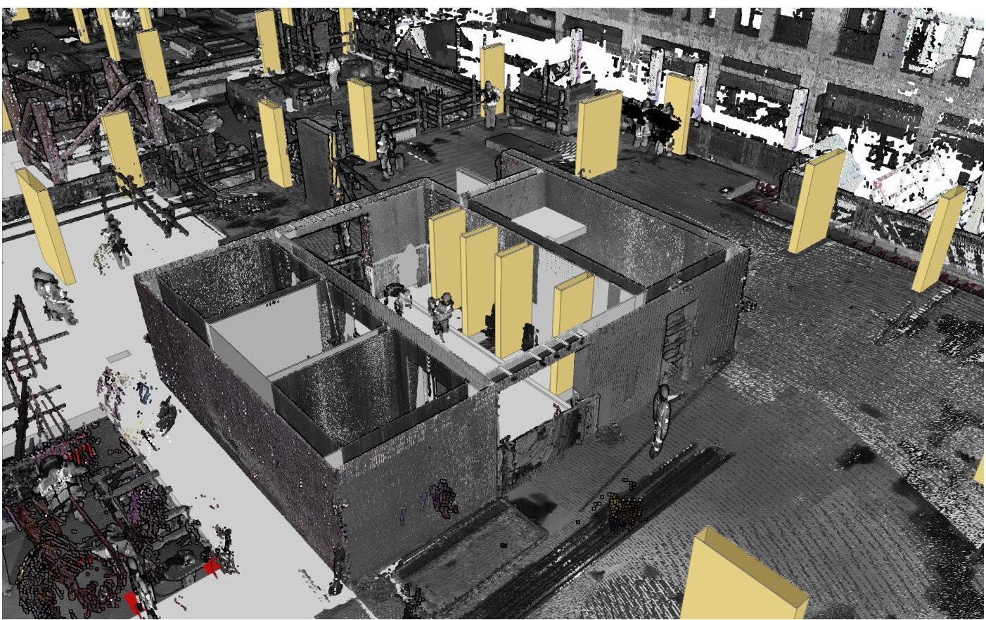
PC Analysis
Visualize the whole structure and identify irregularities which cannot be spotted by a site visit or a traditional survey
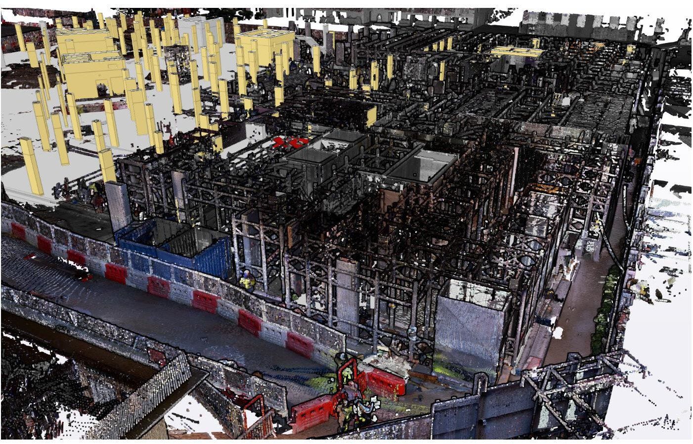
Mechanical Electrical Plumbing (MEP)
The scanned data provides information on the current situation and insight into possibilities for expansion.
Highly accurate 3D laser scanner
Our team uses a high-speed survey-grade 3D laser scanning system which has up to 2mm accuracy and is effective on dark and reflective surfaces undetectable by most other scanners. Depending on project requirements captured point density can be adjusted to meet specification.
Bruno Engineering Ltd
30 Durham Road, SW20 0TW, London

© 2022. The content on this website is owned by us and our licensors. Do not copy any content (including images) without our consent. Privacy Policy | Terms and conditions